Author: sgeorge, Posted on: 31 December 2015 12:58
This looked like it would be a simple, quick project. I've seen quite a few of these around and was intrigued enough to get interested.
Looking over the voltage references, the chips themselves all look very basic at small footprint 8 pins (dip, soic, etc). Voltage in, Voltage out.
The madness is choosing one of them! This is going to be a one off knocked out project, so do I go with a DIP or a SOIC chip? ugh. I wonder if I have any SOIC-8 to DIP adapters, I think I do, and a tiny board to solder it onto.
I was thinking, I would put an LDO onto the voltage input so we are always getting a fixed output, rather than hooking it to the bench meter and getting whatever I punch in. So a 15V LDO, couple of caps, the VREF chip, and that's it.
I have thought about adding a resistor voltage divider so I can get a second value out besides my 10V reference. Ideally I'd like to get it down into the hundreds of millivolts range, like 0.5V (We can use a 19k + 1k divider to get 0.5V)
So, after a lot of looking around I'm going to grab a REF5010ID from Texas Instruments and it has an initial accuracy of 0.05% with TEMPCO of 3PPM / C.
This would be a nice little 10V reference for my meters, obviously a beastly 8.5 digit meter would chew it up and spit it out, but there should be some level of accuracy inherent in the chip.
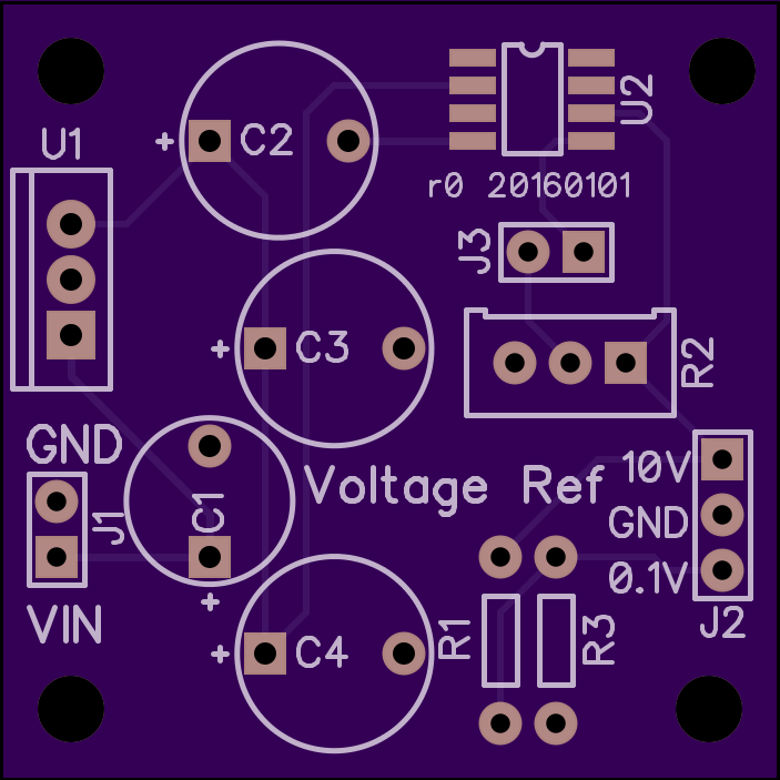
I've roughed out the schematic, its quite small. The challenge now is to find a little project box so I can resize the pcb. I am trying to find a nice metal one, just so its not so flimsy.
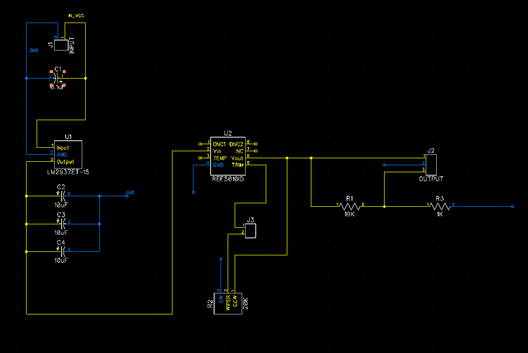
I may change out the 20k trim pot for a 10k trim pot, will see when I test it.
tags: Electronics, REF5010
(dont include links in your comments.)