Author: sgeorge, Posted on: 25 April 2021 11:38
Some action has been had in the Darwin area. After buying a 2.50 ROM upgrade on EBay that was bogus (it is still listed it on EBay), I had to wait a while for another Darwin to appear (and cheaply), and this time it was 2 hours drive away in West Virginia.
This one had two things I needed, the v2.5 ROM and the DSP card!
All I am missing is the SMPTE card.
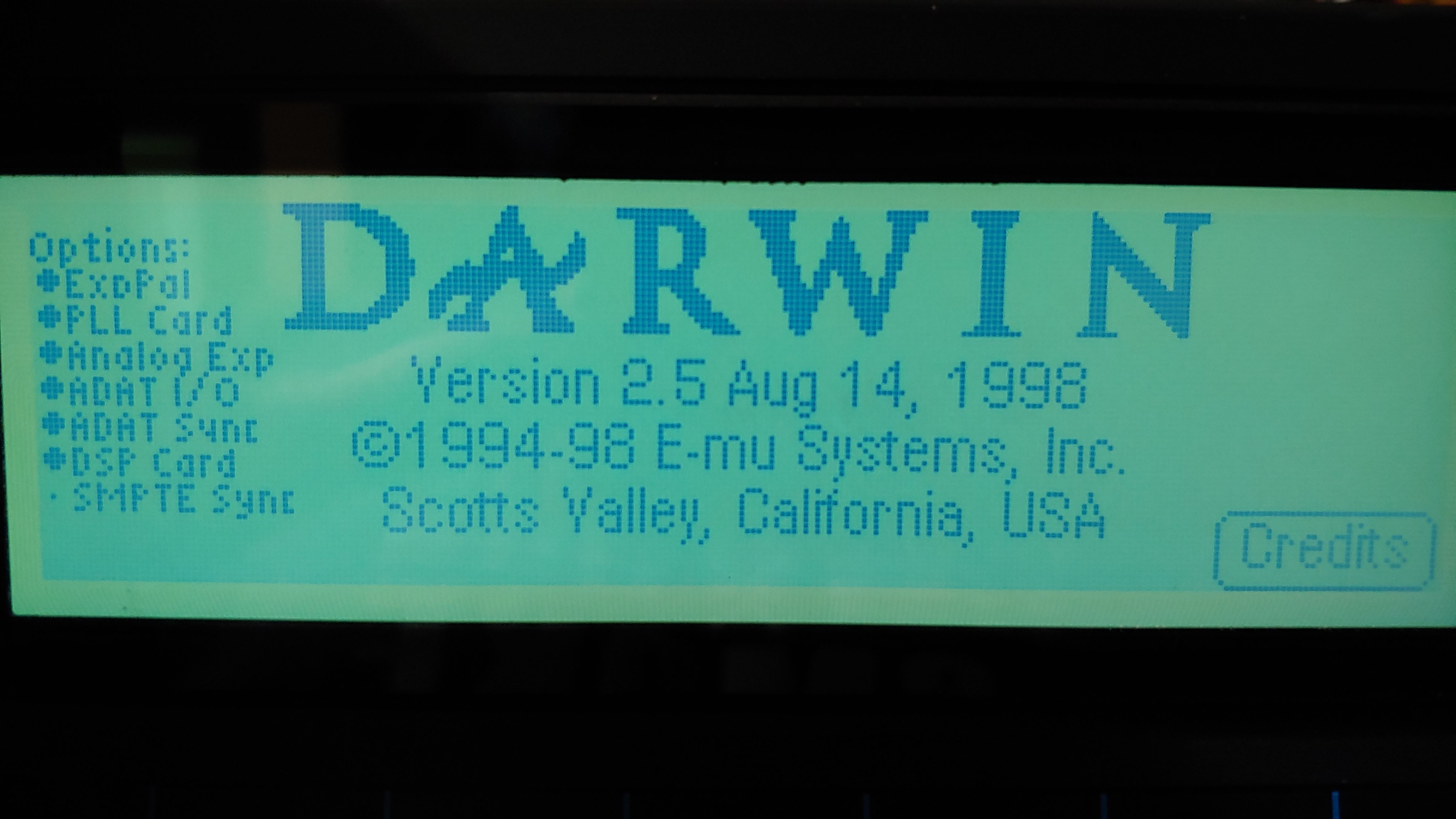
I was able to verify the Test Code password which is 1358, this allows you to get into the testing part of the system.
I have dumped the v2.50 ROM here, as LSB/MSB image and a combined image. You will need two ST 27C4001 EPROMS (512kb each) to burn these.
The nice thing now with v2.5 is I can have (drumroll....) 4gb partition sizes. (which actually exposed a bug in the firmware to me).
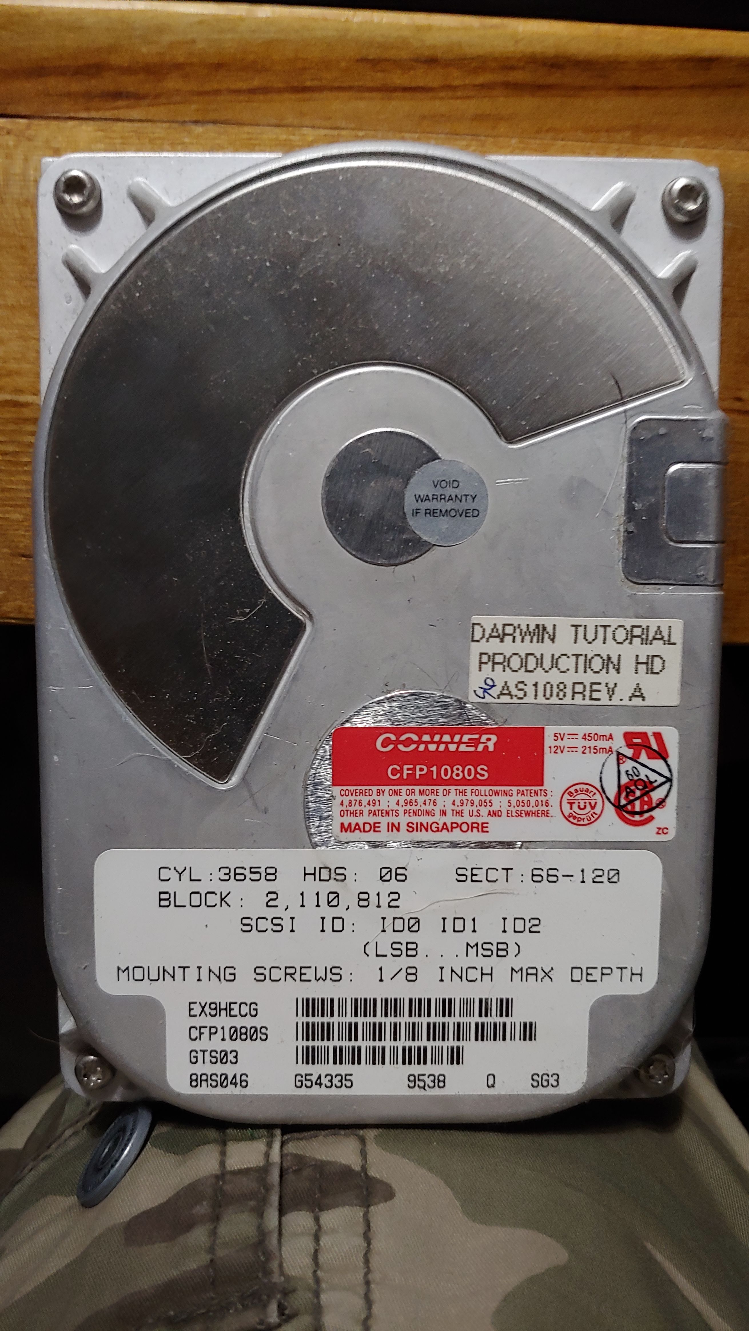
I pulled this from my original darwin, note the sticker "DARWIN TUTORIAL PRODUCTION HD AS108 REV.A"
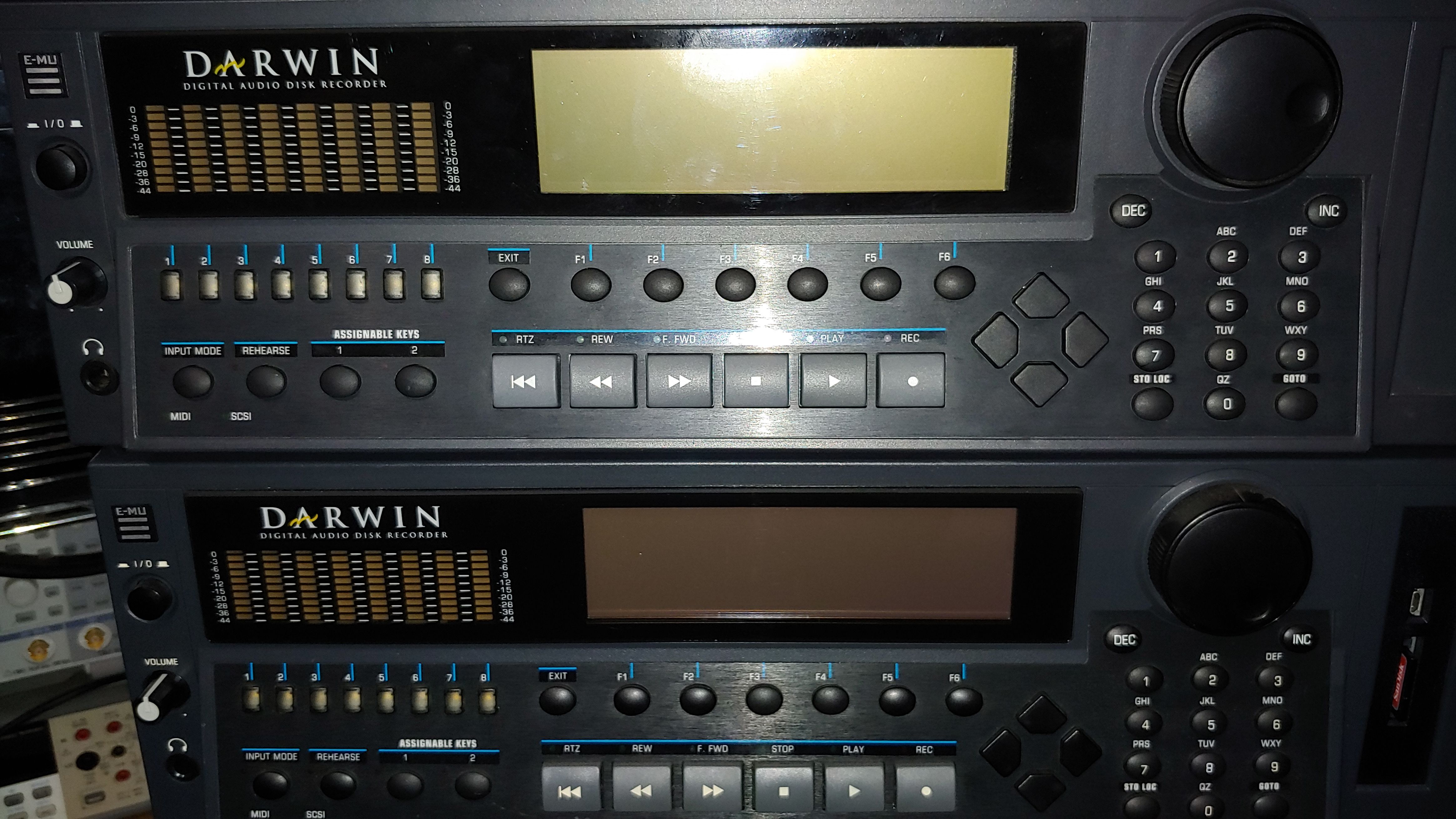
Lets take a closer look at Darwin, as its quite unlike the Samplers.
Like the Samplers, all expansions were decided opon and built into the system from the beginning. You cant add an unknown new expansion to this, say a USB system because its not really got the free IO lines etc.
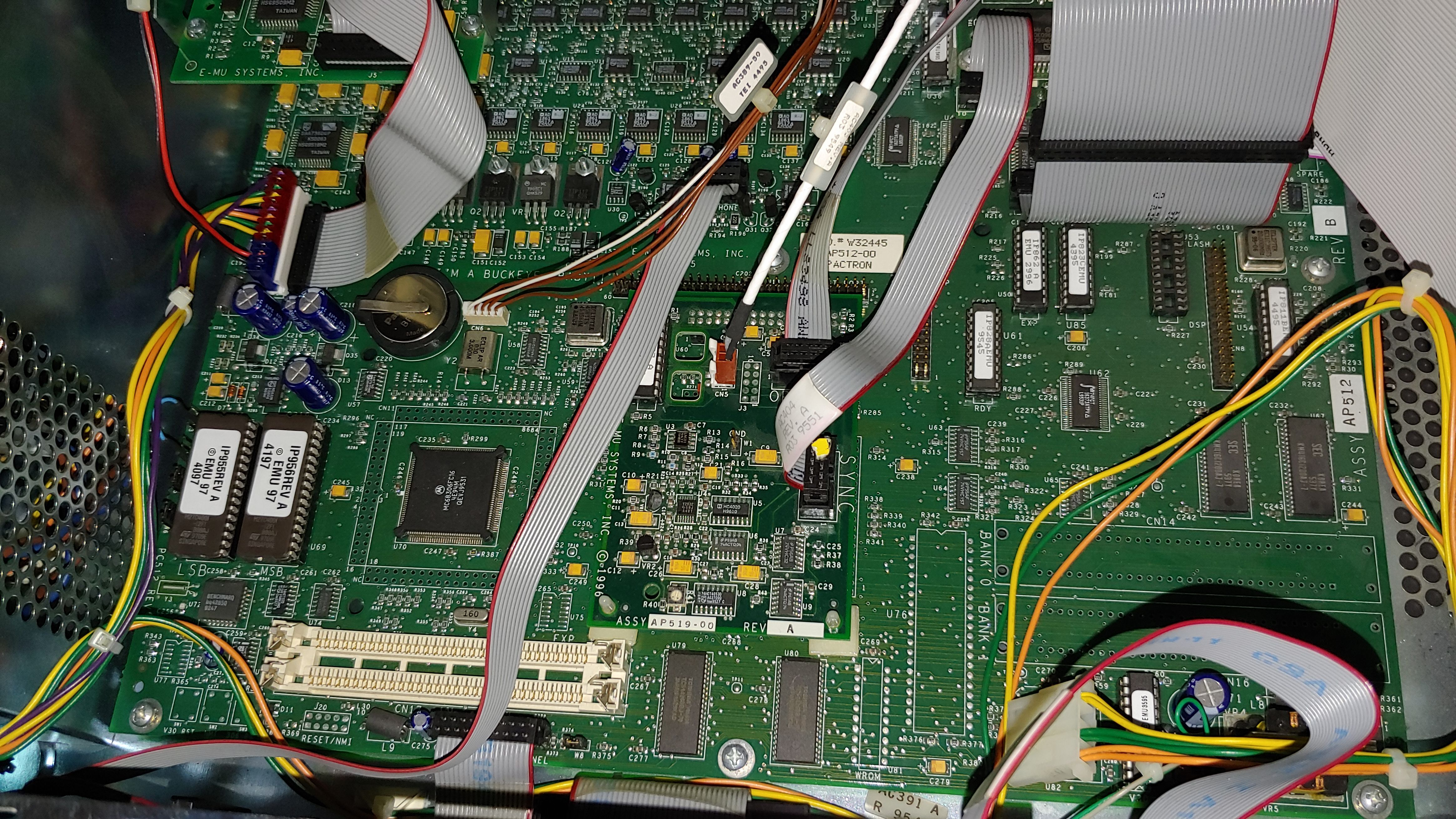
To the bottom left we have the LSB/MSB ROM and the 68k CPU which is a MC68306FC16A which is a plain 68000 EC processor at 16mhz with embedded perhiperals, a DRAM controller and two serial ports.
The DRAM controller can manage 16mb of RAM as 4Mx1 or 64mb as 16Mx1.
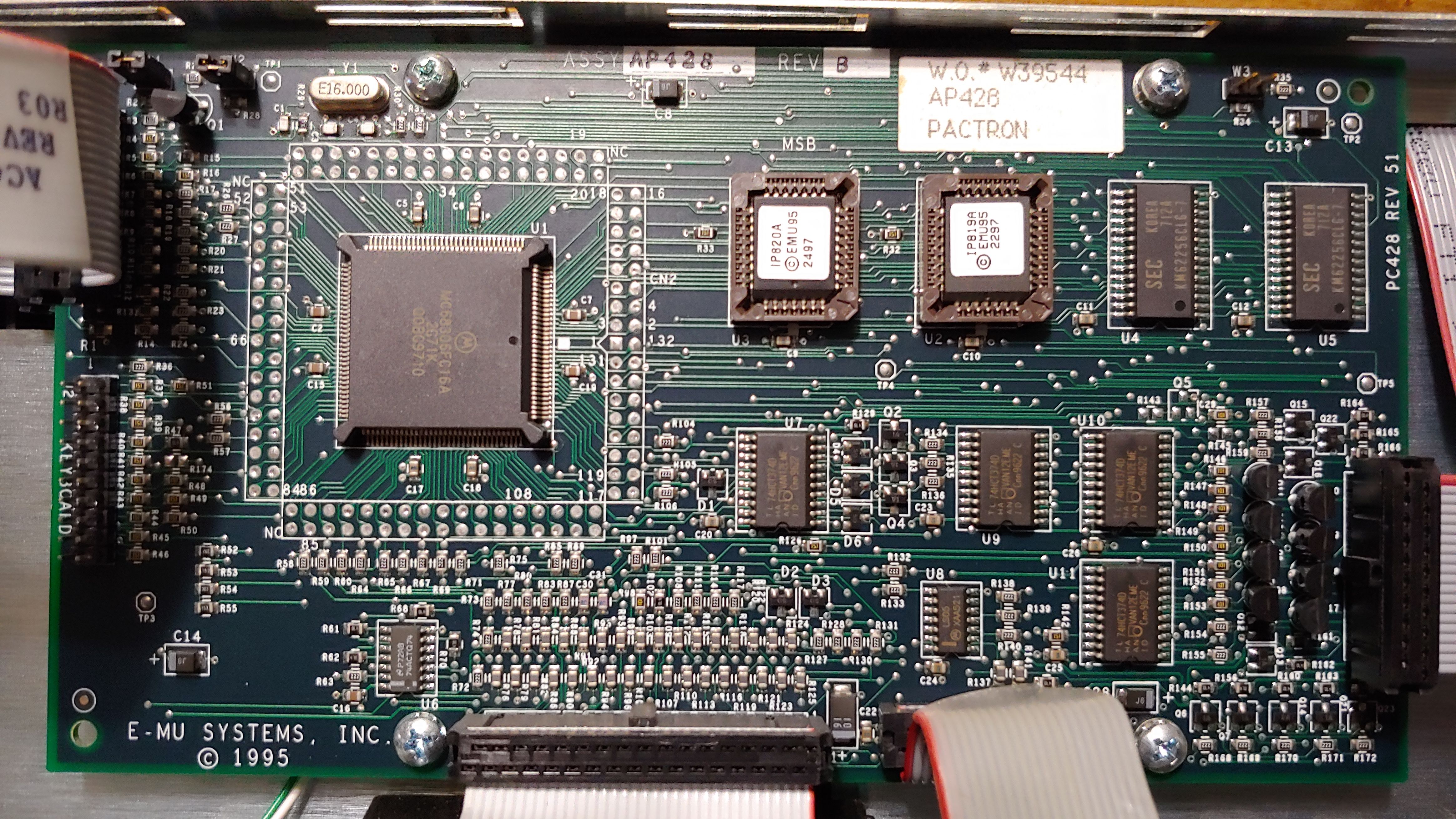
Next to the two 30pin SIMM sockets are two MT4C16257DJ, 256Kx16 fast page RAM chips (4mbit), (meaning 512x16 -> 1mb), and to the far right we have two TMS418160 1Mx16 RAM chips (4mb)
Next to the CPU under the ADAT Optical card is a custom IC,
"AMI 9552AXB 8591-001 IC416 Rev A"
I suspect this is an EMU8000 chip indisguise but I cant prove it.
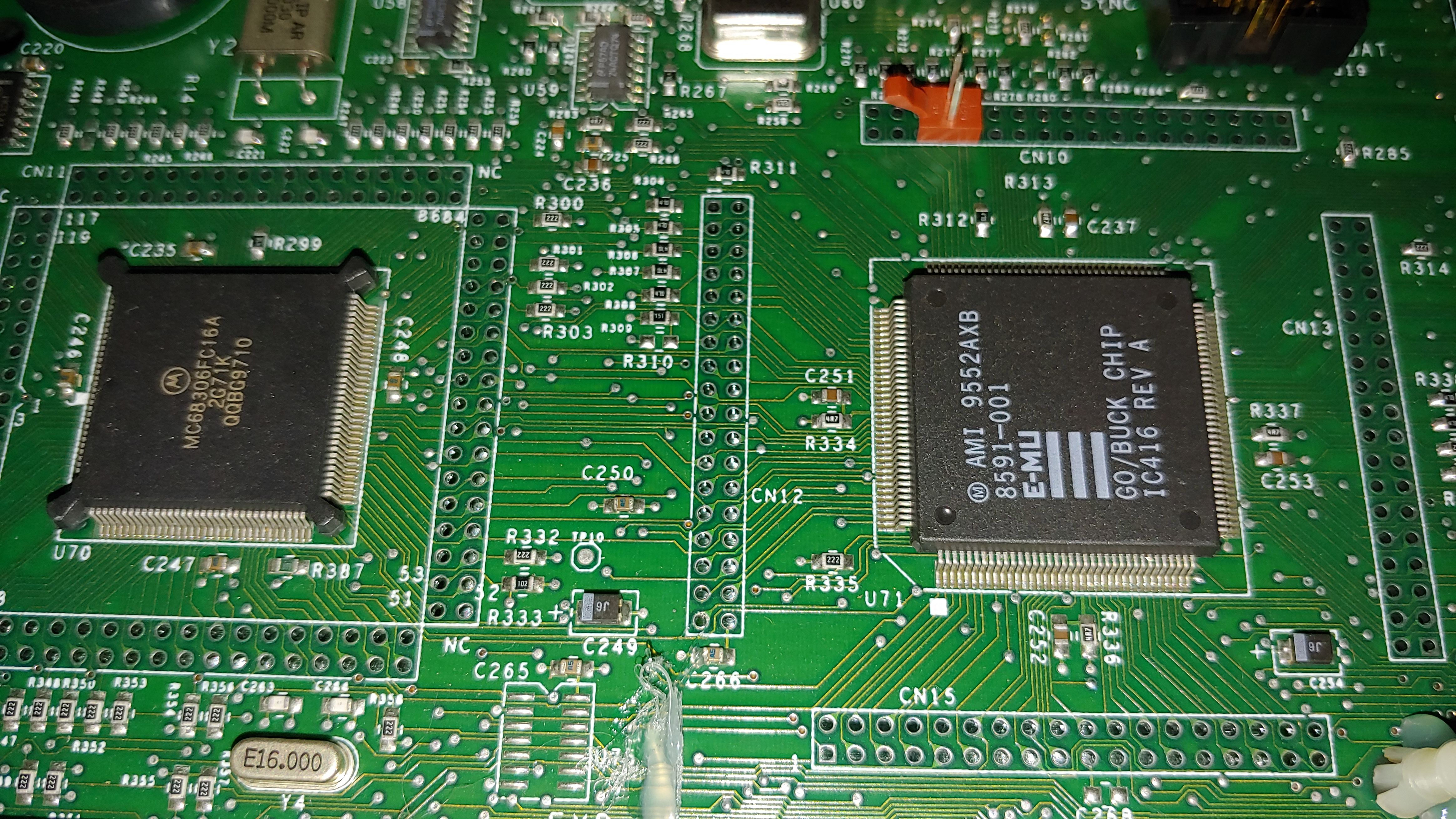
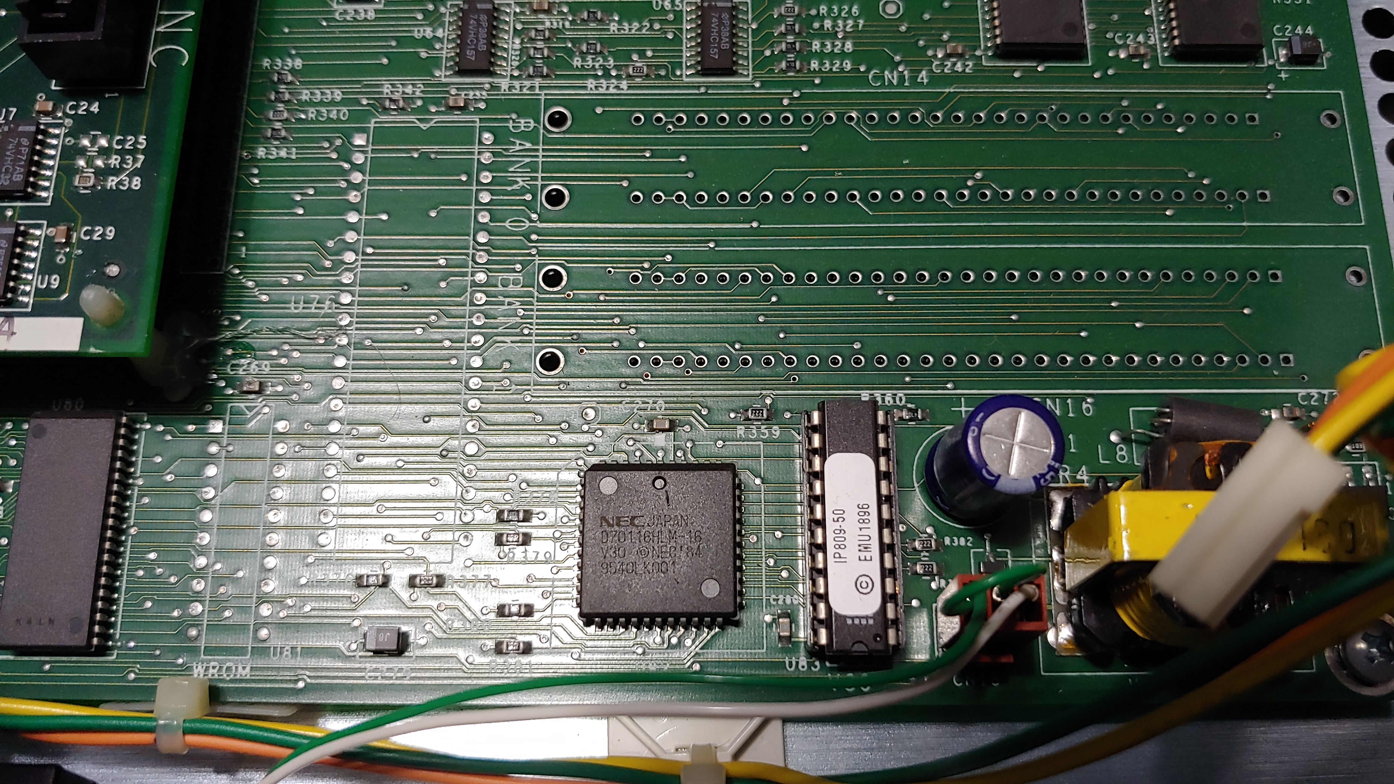
Down in the bottom right we have a strange thing, an NEC V30 CPU (I think the 4mb ram belongs to the V30). The V30 is actually responsible for the SCSI control (There is a Western Digital WDC scsi chip in the back under all the components, so it must act as a control interface offloading it from the main cpu, which makes sense since this is a HD recorder and your streaming audio straight to disk).
Above the V30 are 4 unpopulated 30 pin SIMM sockets, and to its left, I suspect is the pinout for a 40pin DIP version of the CPU instead of the PLCC version actually used.
It also appears to have been designed for a V25 CPU initially (Lots of V25 Disk code mentions in the ROM instead of V30). Looks like the V30 ROM is inside as well,
ROM code Copyright 1988-1995
by Pete Lowe and Audio Digital Systems.
Version 02.00a,08/05/98 19:51
(The Darwin 2.02 ROM contains Version 1.81).
Curious too, the system was initially called "Buckeye"
ADS Inc.Buckeye 8 chan 1.00
and later changed to Darwin
E-mu Darwin 8 chan 1.00
I wonder if they outsourced this project or bought outright another project. V25 CPU would have been really odd since it has only an 8bit externally address bus, where the V30 has a 16bit bus.
It does seem to point to an externally made project brought into E-MU, though not all references were changed as the 2.5 ROM still has a "This isn't a Buckeye backup tape." message.
It seems ADS was a company created by Pete Lowe and John Cook in 1990 and closed in 1998. Only other info I can find is
The 60" excerpt on which the entire work is based was transferred directly
from CD to hard disk using an Audio Digital Systems AES/EBU/SCSI interface
developed at The Ohio State University under a National Endowment for the
Arts Centers for New Music Resources Grant.
So ADS was tied to OSU or something... They also lobbied congress on the DAT law in 1990 (Digital Audio Tape Recorder ACT of 1990).
Anyway, back on track.
The DSP card here as an obvious TI DSP, a TMS320C32PCM 60, a 60mhz DSP. The chip under the sticker is an Altera FPGA.
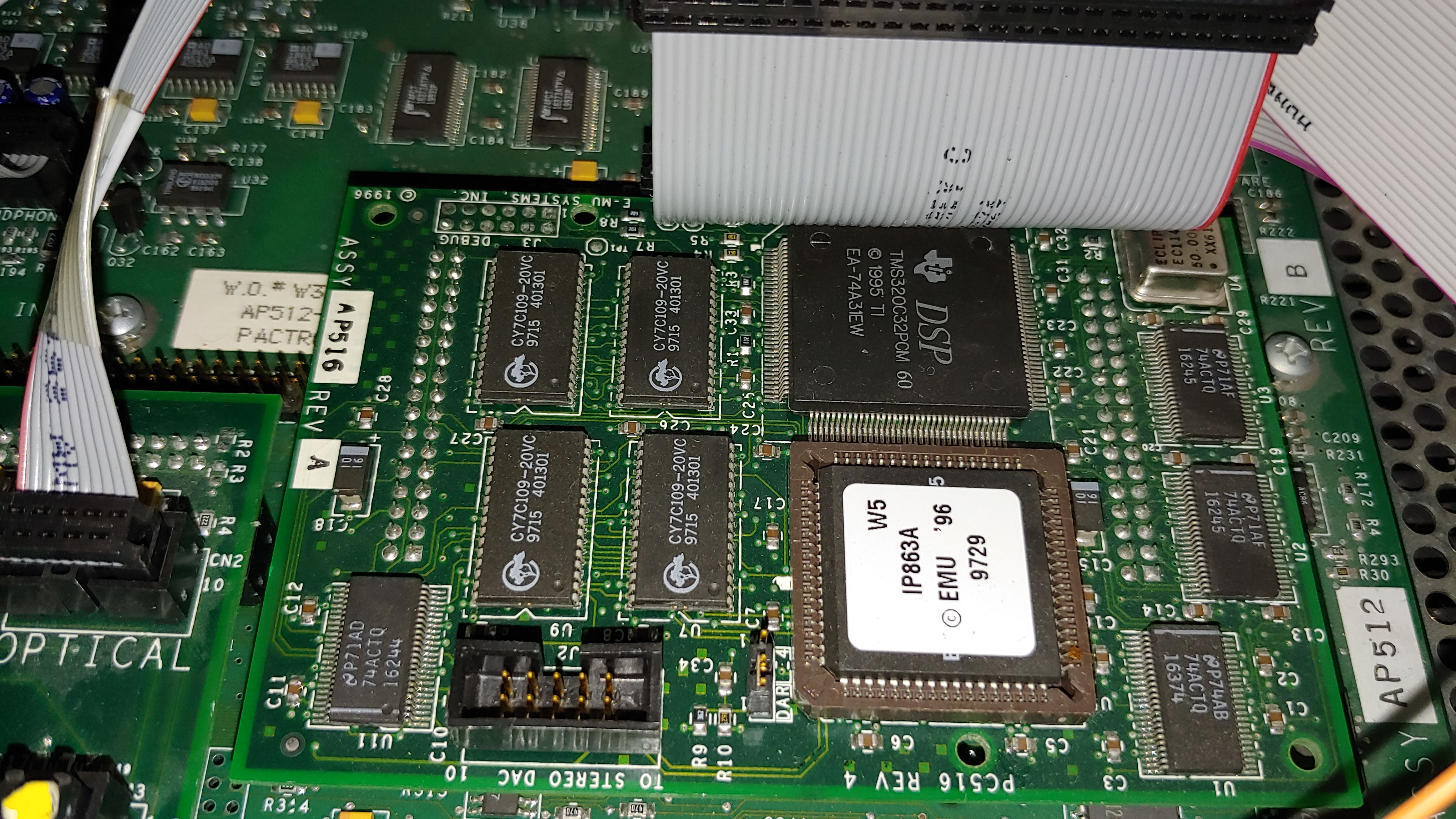
The one other thing ALL over this PCB is Lattice GAL's, programmable logic, which I am really surprised to see (I counted 10).
The back of the display is totally unlike the Ultra Samplers. You can see another MC68306FC16A CPU. The interesting thing (you cant quite see) is a 20 pin header on the left side labled "Keyboard". It appears to have its own RAM + ROM which is very strange.
The display is a Samsung HK333-94V0 using the common Toshiba T6963C chip, same chip in the Ultra Samplers with a 20 pin connector. I'm tempted to put the display into my Ultra.
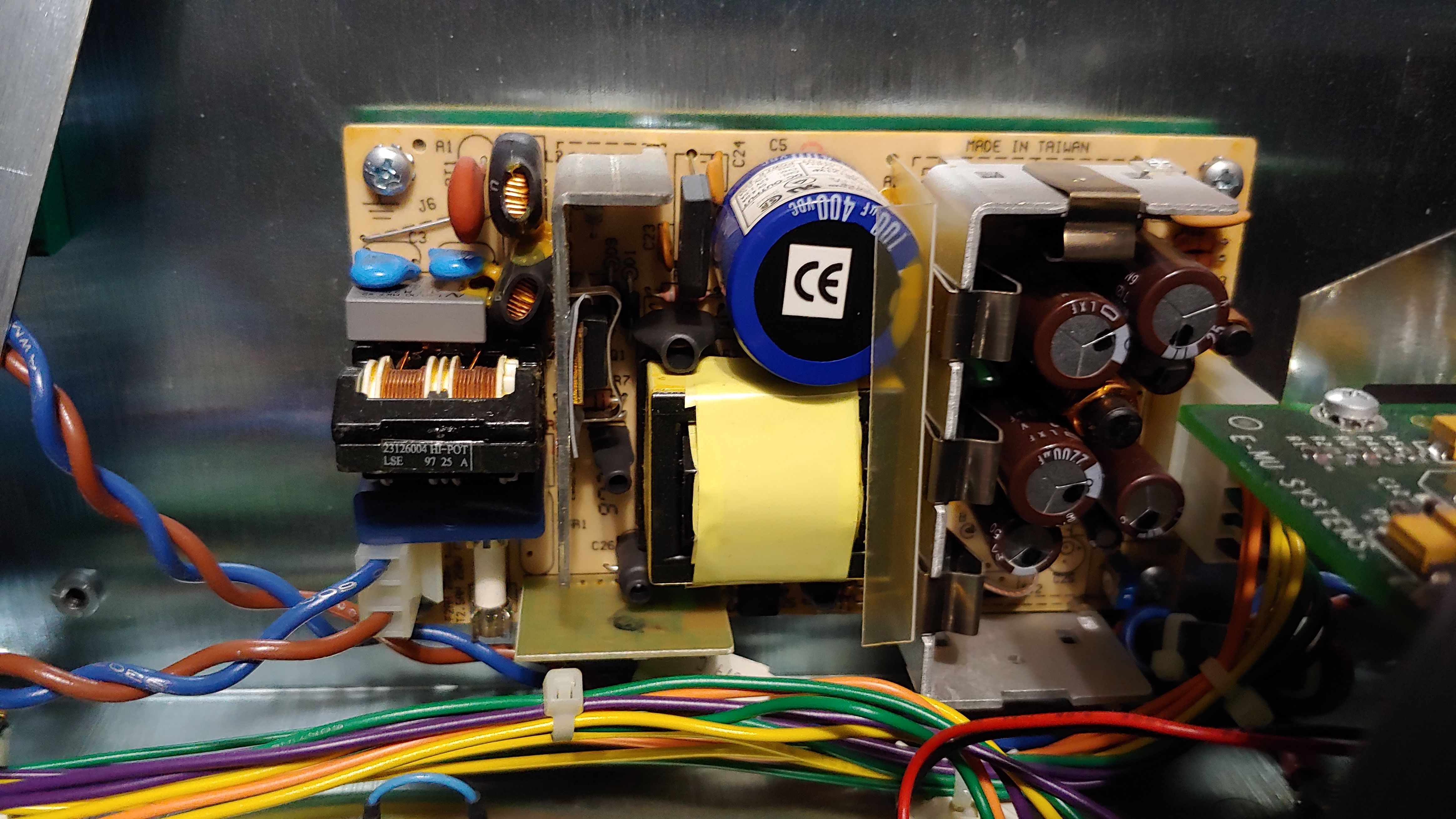
The power supply is a PSA-45A but the sticker says FPS45-051212P, which we have seen in some of the Samplers.
Digging into the ROM I found this credits message (incase you didnt want to watch the scrolly credits all the way through)
CORE DEVELOPMENT TEAM
Scott Ruda
Pete Lowe
Morgan Woodson
Steve Verity
Josh Jeffe

MANAGEMENT
Mike Price
Mike McRoberts
Penny Kleinhans
Bryan Lanser
Matt Ward

MAJOR CONTRIBUTORS
Rob Boyer
Scott Fuller
Mark vonGnechten
Ed Rudnick
Kevin Monahan
Riley Smith
Steve Thompson
Tony Dean
Whitney Preston
Kevin Moore
Conrad Praetzel
Peter Elsea
Terry Grame

ADDITIONAL CONTRIBUTORS
Dan Freeman
Rick Kleffel
Dave Rossum
Michael LaBauve
Brian Hess
Peter Block
Renee O'Regan
Alan Grattan
Danny Gross
Dan Skweir
Chuck Pagano
Steve Spirn
Lenny Collins
Jeff Sumida
Jim Lawton
Tim Prince
Robert Eckert
Justin Mayer

DSP ENGINEERS
Tyler Brown
Mark Dolson
Jean Laroche
Brian Link
Alan Peevers
Even seeing some of the internal commands;
Usage: err { print error status commands }
Usage: DSKOPEN :
Usage: DSKCLOSE :
Usage: MKDIR :PATH
Usage: RMDIR :PATH
Usage: rm [-r] :PATH
Usage:  RENAME PATH NEWNAME
Usage: ls PATH
Usage: CAT PATH
Usage: DUMP PATH
Usage: DUMPDISK device block [count]
Usage: COPY FROMPATH TOPATH
Usage: DIFF PATH PATH
Usage: MKFS dev
Usage: FDISK dev
Usage: FILLFILE PATH PATTERN Short
Usage: riffread path
Usage: disktest [-w] scsiID
usage: foo [value] { set value of foo }
usage: proj path { print path of current project }
usage: adc debug [true|false] { set state adc debugging }
usage: adat debug [flag] [true|false]{ set adat debug flags }
usage: scsi help { report scsi commands }
Usage: sync debug [true|false|level] { set or report sync debug level }
Usage: smpte mode m { set/get controller mode }
There is a lot more stuff buried into the ROM as well, I think if you can connect up to the debug console you can get a lor more stuff out of it.
Here is the v2.5 ROM images emu_darwin_v2_50.zip
Looking this thing over, it would have been very expensive to make with a very large bill of materials, GAL firmwares, FPGA chips, cpu's, ram..
tags: Audio, Darwin, E-MU, Recorder
| Jason said on September 19, 2021 16:44:37; | |
| I have a Darwin with the SMPTE sync option that I’ll never use. Actually I’ll never end up using the Darwin itself. | |
| Fabio said on November 23, 2021 03:08:44; | |
| Hello, I’m Fabio and I own a Darwin with OS 1.02. I have EPROMS of OS 2.50, but I have heard that it’s necessary to change the DIP switch behind the EPROMS (in your photo they are not focused). Could you post a shot of the EPROMS and the DIPs near, so I can see their correct position? Thanks | |
| obsoletemachines said on March 19, 2022 18:24:01; | |
| the internals are closer to the Emu EIV...with the famed analog devices converters, which are much better than the later AKM variety. The input too is Philips bitstream found on Eiv. The DSP is completely different, maybe this is pre ASIC EMU8000. Would be good to see the DSP options | |
| Ivan said on November 27, 2022 15:29:17; | |
| Hi, Can you recommend the exact model of the 2 SIMM chips? | |
| Stu said on December 02, 2022 13:12:32; | |
| Ive found no use of the two simm sockets. Nothing visible suggested any memory I put in them were useful. | |
| Ivan said on December 04, 2022 19:57:00; | |
| Thank you. | |
Entry too old for new comments.